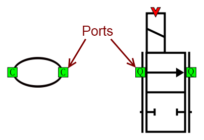
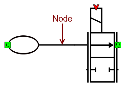
Models must be built according to the transmission line element method. You are advised to read the section on this before you begin.
The first thing you need to do is create a new model, if you have not already done so. Click on File->New->Project, or press the New button in the toolbar. An empty model should now be visible in the workspace area.
Adding Components
Next step is to add the components. To do this, you first need to find the components in the library. Standard components are divided into three libraries; hydraulic, mechanic and signal. These can in turn be filtered by different usages. When you have located the component you want, it can be added to your model by dragging it from the library to the workspace. The new component appear where you drop it, and can then be moved, rotated and flipped to a wanted position.
Connecting Components
Components in HOPSAN are connected by creating a node between two or more ports. In the graphical interface, a node is represented by a connector, represented by a line in the workspace. The color and style of the line tells of which type the node is. A black line represent bi-directional energy transmitting nodes (for example hydraulic or mechanic connections), while blue dotted lines represent uni-directional signal connections.
The connection is created by clicking on one of the ports, drawing the connector the way you want it and finally clicking on the end port. Most ports, but not all, must be connected before simulating the model. Note that the TLM method results in that C-type components, such as volumes, can only be connected to Q-type components, such as valves or orifices. This can feel a little tricky, but is on the other hand always physically motivated. Signal components are simulated sequentially and do not obey these rules.


Changing Component Parameters
To change parameters of a component, you can double-click on it to open its parameter dialog box. Here it is possible to change the name of the component and its parameters. If the component is of C-type or signal type it is also possible to adjust the start values for its connected nodes. Erroneous start values can potentially cause unwanted behavior such as "jump steps" at the beginning of the plots.
Using Global Parameters
Global system parameters can be used to quickly change a parameter value in several components at once. To do this, open the System Parameters widget by clicking on the little earth globe icon in the toolbar or by pressing Ctrl+Alt+Y.
| System Parameters |
From here new system parameters can be added or removed by clicking on the "Set" and "Unset" buttons. Values can be changed directly by double-clicking on their values in the list. They can then be used as parameters in components by clicking on the icon to the right of the parameter value box in the component's parameter dialog. When a system parameter is changed, it is changed for all components that use it. Should a system parameter be removed, the components that use it will change to simply using the last numerical value of the parameter instead.
Subsystems
Parts of a model can be converted to subsystems, by adding a Subsystem component from the subsystems library. This works as a component that can contain other components (and other subsystems). Subsystem ports are defined by adding Container Port components inside it. When connecting to a component on the inside, the outside port will change its type and vice versa.
Subsystems offers several interesting features. They can for example have smaller time steps (even multiples) than the one in the parent system. They can also be loaded from external model files, and thereby be shared between several models. System parameters can also propagate downwards from parent systems to subsystems.
Because subsystems works as a component, the C, Q or S type is important. It is not possible to connect two container ports to both C- and Q-type components in the same subsystem. This will result in an invalid type, and the model cannot be simulated.
Widgets
To make models more nice looking and understandable, it is possible to add text box widgets. These are purely cosmetic and do not modify the behavior of the system in any way. To add a widget, simply right click on the workspace and select "Add Text Box Widget" from the pop-up menu.
A new widget will then appear at the menu position. It contains of two parts, a text and a box. The text is always located in the upper left corner. Its appearance can be modified by double clicking on it. The box can be resized by dragging the lines with the mouse. A pure text widget or a pure box widget can be created by removing the box or the text from a text box widget.